CUSTOM SHIP MODEL MANUFACTURING
How to Turn GA Drawings into an Accurate Scale Ship Model
A general arrangement (GA) drawing is one of the most useful starting points for creating a vessel-specific scale model. It provides essential information about the vessel's overall layout, deck levels, superstructure, working areas and major equipment.
However, turning an engineering drawing into a physical model requires more than reducing its dimensions. The design must be interpreted, scaled, checked against other references and translated into components that can be manufactured and assembled.
In this guide, we explain how professional ship model manufacturing transforms GA drawings into detailed models for shipowners, shipyards, marine engineering companies and corporate displays.
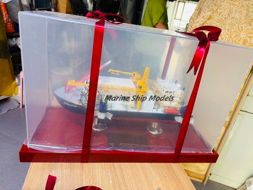
1. Understand What a GA Drawing Can Tell You
A general arrangement drawing shows how the principal spaces and structures of a vessel are organized. Depending on the drawing package, it may identify accommodation blocks, bridge positions, deck levels, cargo areas, machinery zones, access routes and major equipment.
For a scale model manufacturer, this information helps establish the vessel's overall proportions and the relative position of important structures. It is especially valuable when reproducing a specific commercial ship, offshore vessel, tugboat or specialist marine platform.
Overall Configuration
Identify the hull outline, deck arrangement, bridge location, superstructure, stern and major external structures.
Equipment Position
Determine the approximate location of cranes, lifeboats, winches, hatches, masts and other recognizable components.
Principal Dimensions
Use length, beam, height and other available measurements to check the model's proportions.
Additional References
Identify which areas require profile drawings, deck plans, equipment drawings or photographs for clarification.
For more information about how source drawings are used, explore our ship model manufacturing guide.
2. Review the Complete Drawing Package Before Production
A GA drawing is an excellent starting point, but it may not contain every detail needed for a highly accurate physical model. The available information should be reviewed before the design moves into production.
- GA plan: overall vessel configuration and major structural relationships.
- Side profile and elevations: hull profile, deck heights, bridge levels and superstructure.
- Deck plans: equipment locations, access arrangements and working areas.
- Equipment drawings: specialist cranes, winches, masts or offshore systems.
- Photographs: real-world colors, windows, railings, markings and external appearance.
- CAD files: additional dimensional and geometric references, where suitable.
For shipyard and newbuilding projects, drawings can often be combined with project renderings, vessel specifications and approved branding files. See our marine industry applications for examples of how custom ship models support professional presentations.
Practical tip: Send the latest approved drawings whenever possible. If the vessel design has changed, identify which revision should be followed and highlight any structures that must be reproduced exactly.
3. Calculate the Correct Model Scale
Scale determines how the full-size vessel is translated into a manageable physical model. The selected ratio must match the required display space, expected detail level and intended application.
Model length = Original vessel length ÷ Scale denominator
For example, a vessel measuring 200 metres would have an approximate model length of:
- 1:100 scale — 200 cm
- 1:200 scale — 100 cm
- 1:400 scale — 50 cm
These figures represent the vessel length only, excluding the display base and protective case.
Length alone does not determine the best scale. A vessel with complex cranes, pipes, railings or offshore equipment may require a larger model to preserve the visibility of key details.
Use our Marine Ship Models website to explore custom vessel projects, or review the scale guide for additional guidance on scale selection.
4. Translate the Drawings into a Model Design
Once the reference package and scale have been reviewed, the next step is to interpret the vessel's geometry and define the structures and components that will make up the model.
STAGE 01
Hull Geometry
Establish the hull's main proportions, bow and stern profiles, beam, waterline and overall silhouette.
STAGE 02
Superstructure
Develop the bridge, accommodation blocks, decks, windows and external platforms.
STAGE 03
Deck Components
Plan cranes, hatch covers, lifeboats, winches, pipes and other vessel-specific equipment.
STAGE 04
Visual Identity
Record vessel names, hull markings, logos, paint colors and other recognizable details.
CAD, 3D modeling, CNC processing and 3D printing may be used where appropriate. The production method depends on the geometry, material, required finish and size of individual components. Hand assembly and finishing remain important for many small marine details.
5. Pay Attention to Detail at the Selected Scale
Not every feature in a full-size engineering drawing can be reproduced at the same physical thickness or level of complexity. Some details become extremely small after scale conversion, so the manufacturer must determine how to preserve their appearance without compromising structural integrity.
- Railings and ladders: balance visual accuracy with strength and handling requirements.
- Windows and bridge details: follow available elevations and photographs.
- Deck machinery: reproduce the major shapes and positions of cranes, winches and other equipment.
- Lifeboats and davits: check locations, orientation and supporting structures.
- Painting and markings: use supplied color references, logos and vessel identification.
For a commercial vessel, a correct hull and superstructure may establish the overall identity, while specialized equipment can be essential for recognizing an offshore or engineering vessel. The detail priorities should therefore reflect the actual project rather than a generic template.
6. Manufacture, Assemble and Finish the Model
After the design and component plan have been reviewed, the project moves into physical production. Depending on the vessel and model specifications, the process may include hull fabrication, deck and superstructure construction, individual component manufacturing, assembly, surface preparation, painting and installation of fine details.
Before finishing, the main structures should be checked against the approved references. This helps identify proportion errors, misplaced equipment or inconsistencies between different drawing views before they become difficult to correct.
Our ship model making article provides further background on the overall production process.
7. Inspect the Finished Model Against the Original References
A professional inspection should assess more than the general appearance. It should also consider the vessel's defining proportions, structural arrangement, equipment positions and visual identity.
- Are the hull proportions and superstructure positions consistent with the drawings?
- Are the major deck structures and equipment located correctly?
- Do the paint scheme, vessel name and markings match the supplied references?
- Are small components securely assembled and properly finished?
- Is the model prepared for its intended display and transportation requirements?
For large, fragile or technically complex projects, protective packaging should also be considered early in the planning process.
8. What Should You Send to a Ship Model Manufacturer?
You do not necessarily need every document listed below to begin a discussion. Send the available information so the manufacturer can assess the project and identify any missing references.
Technical Information
- GA drawings and deck plans
- Side elevations and equipment drawings
- CAD files, if available
- Vessel dimensions and name
Project Requirements
- Preferred scale or model length
- Required quantity
- Photographs and color references
- Company logo and markings
- Display and delivery requirements
These details help establish the project scope and allow the manufacturer to recommend a practical model size, production approach and quotation.
Turn Your GA Drawings into a Custom Ship Model
Whether you are commissioning a vessel delivery model, a corporate display piece or a technically detailed marine model, the first step is to review the drawings and define the project requirements.
Send your GA plans, vessel photographs, dimensions, preferred model scale and quantity for an initial project review.
Request a Custom Model Quote
Explore Marine Applications
Frequently Asked Questions
Can you make an accurate ship model from GA drawings alone?
A GA drawing can provide a useful foundation, especially for the vessel's general arrangement. The achievable detail depends on the information available, vessel complexity and desired scale. Additional elevations, deck plans and photographs can help resolve missing information.
Are photographs necessary if I already have engineering drawings?
Not always, but photographs can help clarify colors, external fittings, markings and the appearance of equipment that may not be fully represented in the drawings.
Can CAD or 3D files be used instead of GA drawings?
Suitable CAD or 3D files can support dimensional and geometric interpretation. Their usefulness depends on the file format, model content and whether the geometry accurately represents the vessel. Additional drawings may still be needed.
How do I choose the right scale for a custom ship model?
Consider the original vessel dimensions, required finished length, available display space, visibility of small details and intended application. A manufacturer can review these factors before recommending a practical scale.
What is the first step in requesting a custom ship model?
Send the available GA drawings, photographs, vessel dimensions, preferred model size or scale, quantity and delivery destination. The manufacturer can then review the project requirements and advise on the next steps.



 Deutsch
 English
 Dansk
 한국어
 Français
 Italiano
 Suomi
 Bahasa Indonesia
 日本語
 Polski
 Português do Brasil
 简体中文
 Türkçe